
⚡ SOLAR ELECTRICAL DESIGN & IMPLEMENTATION
Safe, Efficient and Professionally Engineered Solar Power Systems
Even the highest-quality solar panels and inverters cannot deliver reliable performance if the electrical system is incorrectly designed, improperly protected or poorly installed.
At Ittehad Solar Energy, our electrical design and implementation process focuses on system safety, energy production, equipment compatibility, protection, reliability and long-term performance.
From the first load survey to final testing and commissioning, every stage should be planned according to the property’s actual energy requirements.
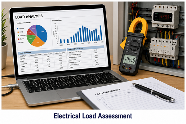
1. Electrical Load Assessment
The process begins with understanding how electricity is being used at the property.
Our assessment may include:
- Existing electricity bills
- Sanctioned or connected load
- Maximum demand
- Daytime and nighttime consumption
- Single-phase or three-phase supply
- Essential and non-essential appliances
- Motor, pump and compressor loads
- Air-conditioning requirements
- Starting current of heavy equipment
- Seasonal changes in electricity use
- Existing generator or UPS system
- Future load expansion
This information helps us recommend a system based on actual requirements rather than assumptions.
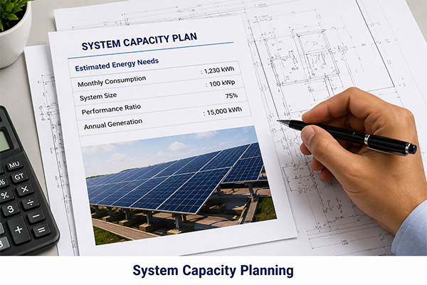
2. Solar System Capacity Planning
System capacity is selected after studying:
- Available installation area
- Electricity consumption
- Daytime load
- Desired reduction in electricity bills
- Available grid connection
- Backup requirements
- Battery-storage requirements
- Inverter operating limits
- Future energy requirements
- Project budget
The proposed capacity should be technically practical and economically beneficial.
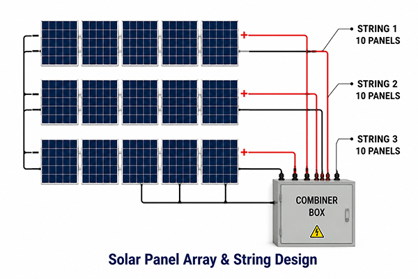
3. Solar Panel Array and String Design
Solar panels are connected in groups called strings. The number of panels in each string must match the electrical limits of the selected inverter.
Our design process considers:
- Solar panel voltage
- Solar panel current
- Open-circuit voltage
- Short-circuit current
- Inverter MPPT voltage range
- Maximum inverter DC voltage
- Maximum MPPT input current
- Temperature-related voltage changes
- Number of panels per string
- Number of strings per MPPT
- Orientation and shading differences
Incorrect string sizing may reduce production, create inverter faults or expose equipment to excessive voltage.
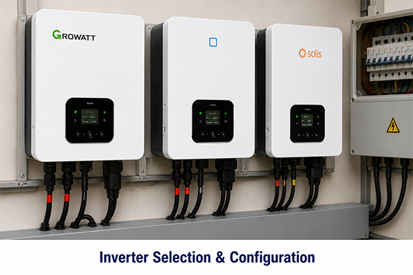
4. Inverter Selection and Configuration
The inverter converts the DC electricity produced by solar panels into usable AC electricity.
The selection process considers:
- Required system capacity
- Single-phase or three-phase operation
- Number of MPPT inputs
- Solar-array compatibility
- Grid-tied, hybrid or off-grid operation
- Battery compatibility
- Required backup output
- Monitoring features
- Environmental installation conditions
- Warranty and after-sales support
- Future expansion possibilities
The inverter must be correctly matched with the solar panels, electrical supply and customer’s energy objectives.
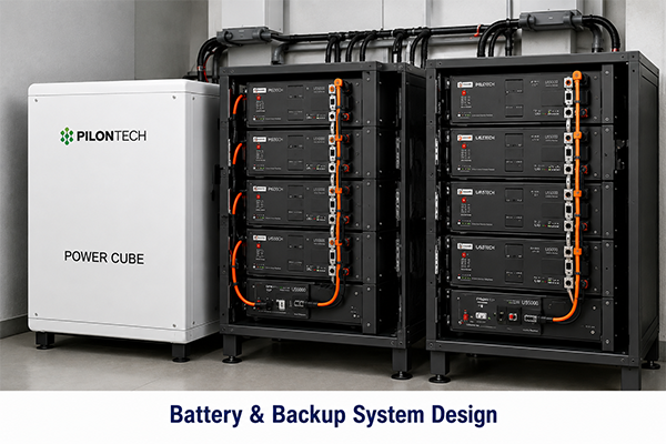
5. Battery and Backup-System Design
For customers requiring backup during power outages, the system may include lithium or other suitable battery storage.
Battery design considers:
- Essential backup load
- Required backup duration
- Battery voltage
- Usable battery capacity
- Maximum discharge current
- Inverter-battery compatibility
- Battery-management system communication
- Charging power
- Available solar energy
- Grid-charging requirements
- Space, ventilation and environmental conditions
- Future battery expansion
Customers can choose between essential-load backup and larger backup systems designed to support a greater portion of the property.
6. Single-Line Diagram and Electrical Documentation
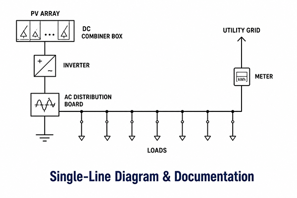
A professional solar project should have clear electrical documentation.
The electrical design may include:
- Single-line diagram
- Solar-panel string layout
- Inverter connection arrangement
- DC distribution arrangement
- AC distribution arrangement
- Cable sizes
- Breaker ratings
- Isolator locations
- Surge-protection devices
- Earthing arrangement
- Metering connection
- Battery connection
- Equipment labels
- Emergency shutdown information
This documentation supports safe installation, maintenance, inspection and future troubleshooting.
7. DC Cable Selection and Routing
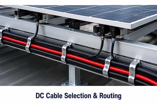
The DC side of a solar system remains energised whenever sunlight reaches the panels. It therefore requires careful design and installation.
Our planning considers:
- Solar-rated DC cable
- Correct conductor size
- Current-carrying capacity
- Voltage drop
- Temperature exposure
- Cable length
- UV resistance
- Mechanical protection
- Correct polarity
- Secure cable routing
- Suitable connectors
- Separation from sharp surfaces and hot areas
Cables should be properly supported and must not be left hanging beneath solar panels.
8. AC Cable and Distribution Design
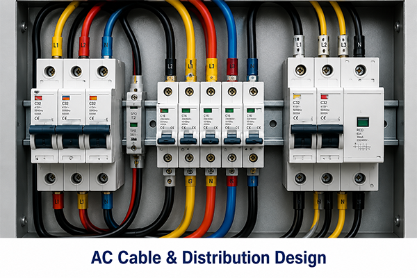
The AC connection carries energy from the inverter to the property’s distribution system.
The design considers:
- Inverter output current
- Cable length
- Conductor material
- Voltage drop
- Installation method
- Ambient temperature
- Existing distribution-board capacity
- Main breaker rating
- Available fault level
- Single-phase or three-phase balancing
- Connection point
- Future expansion
Correct cable and breaker selection helps prevent overheating, nuisance tripping and unnecessary energy losses.
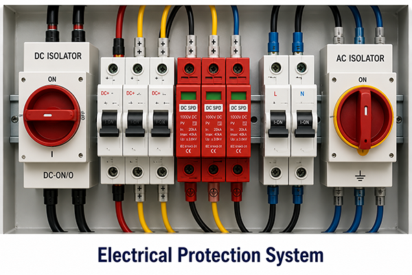
9. Electrical Protection System
Every solar installation requires properly selected protective equipment.
Depending on the system, protection may include:
- DC isolators
- AC isolators
- DC circuit breakers
- AC circuit breakers
- String fuses
- Surge-protection devices
- Residual-current protection where required
- Overcurrent protection
- Short-circuit protection
- Reverse-polarity protection
- Earth-fault protection
- Anti-islanding protection
- Battery fuses or breakers
- Emergency shutdown arrangements
Protection devices must be correctly rated and installed at appropriate locations.
10. Earthing and Lightning Protection
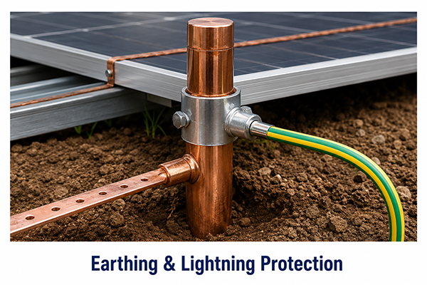
A solar installation must have an effective earthing arrangement.
The design may include:
- Earthing of solar-panel frames
- Earthing of the mounting structure
- Inverter earthing
- AC distribution-board earthing
- Equipment bonding
- Earth electrodes
- Correct earth conductors
- Surge-protection coordination
- Lightning-risk assessment
- Integration with the building’s existing earthing system
Proper earthing helps protect people, property and electrical equipment.
11. Distribution-Board Integration
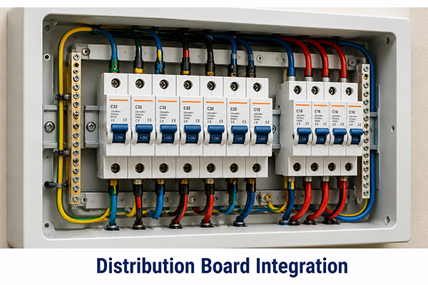
Before connecting the solar inverter, the existing electrical distribution system should be inspected.
The inspection considers:
- Condition of the main distribution board
- Existing breaker ratings
- Available connection capacity
- Cable condition
- Neutral and earth arrangement
- Phase balancing
- Existing generator or UPS connections
- Changeover arrangements
- Space for additional protection devices
- Required upgrades or replacement
Connecting a solar system to an unsuitable distribution board may create serious safety and performance problems.
12. Net-Metering or Prosumer-Ready Design
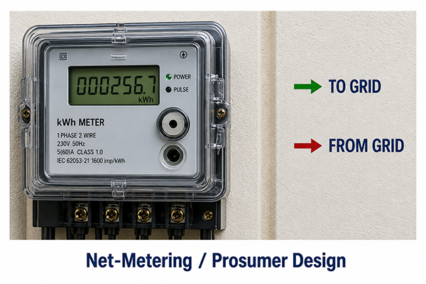
For eligible grid-connected projects, the system may be prepared according to applicable utility and regulatory requirements.
This can involve:
- Approved connection arrangement
- Bidirectional metering preparation
- Single-line diagrams
- Inverter technical information
- Protection details
- Load and generation information
- Required applications and documentation
- Utility inspection preparation
- Safe grid synchronisation
- Anti-islanding functionality
Technical and commercial requirements can vary according to the project capacity, utility company and regulations applicable at the time of application.
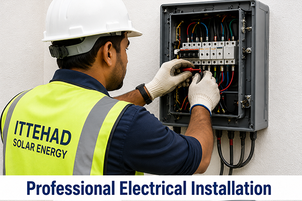
13. Professional Electrical Installation
During implementation, our team focuses on:
- Correct panel-string connections
- Verified polarity
- Proper connector crimping
- Secure cable management
- Labelled DC and AC circuits
- Correct breaker and isolator installation
- Safe inverter mounting
- Protection from heat and moisture
- Proper battery connections
- Clean distribution-board integration
- Accurate torque on electrical terminals
- Safe shutdown arrangements
Neat installation is not only about appearance. It makes the system safer and easier to maintain.
14. Testing and Commissioning
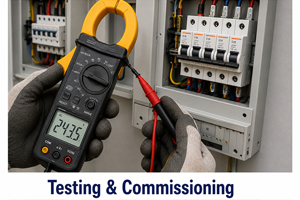
Before the solar system is handed over, electrical tests and operational checks should be completed.
These may include:
- Visual inspection
- Polarity verification
- String voltage measurement
- String current comparison
- Continuity testing
- Insulation testing
- Earthing checks
- Breaker and isolator operation
- Inverter startup
- Grid-voltage and frequency verification
- Battery charging and discharging tests
- Backup-output testing
- Monitoring-system configuration
- Shutdown and restart testing
- Verification of alarms and fault messages
Commissioning confirms that the system has been installed correctly and is operating safely.
15. Monitoring and Customer Handover
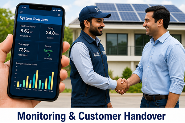
After commissioning, customers should understand how to operate and monitor their system.
Handover may include:
- Inverter operating instructions
- Mobile-monitoring application setup
- Explanation of solar production
- Explanation of grid import and export
- Battery-status monitoring
- Alarm and fault guidance
- Safe shutdown procedure
- Cleaning recommendations
- Maintenance schedule
- Warranty documentation
- Electrical drawings and equipment details
A properly documented handover makes long-term operation easier and safer.
Why Professional Electrical Engineering Matters
Poor electrical design can result in:
- Low solar production
- Excessive voltage drop
- Overheated cables
- Repeated inverter faults
- Damaged connectors
- Unsafe battery operation
- Electric-shock risk
- Fire risk
- Distribution-board failure
- Equipment damage
- Difficult maintenance
- Loss of system availability
Professional electrical engineering ensures that every component works safely and efficiently as part of one complete energy system.